
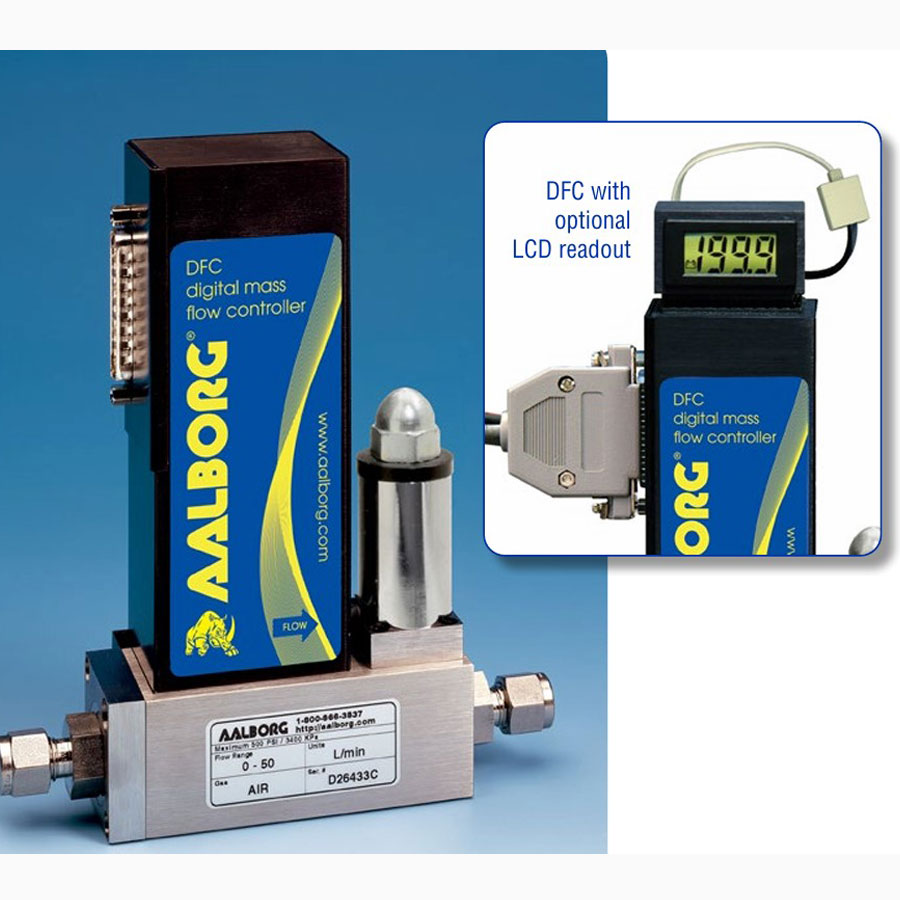
DFC DIGITAL MASS FLOW CONTROLLER
Principles of Operation
Metered gases are divided into two laminar flow paths, one through the primary flow conduit, and the other through a capillary sensor tube. Both flow conduits are designed to ensure laminar flows and therefore the ratio of their flow rates is constant. Two precision temperature sensing windings on the sensor tube are heated, and when flow takes place, gas carries heat from the upstream to the downstream windings. The resultant temperature differential is proportional to the change in resistance of the sensor windings. A Wheatstone bridge design is used to monitor the temperature dependent resistance gradient on the sensor windings which is linearly proportional to the instantaneous rate of flow. The output of the Wheatstone bridge is converted to digital format with a 12 Bit ADC (analog to digital converter). An on-board microprocessor and non-volatile memory store all calibration factors and directly control a proportionating electromagnetic valve. The digital closed loop control system continuously compares the mass f low output with the selected flow rate. Deviations from the set point are corrected by compensating valve adjustments, with PID algorithm thus maintaining the desired flow parameters with a high degree of accuracy. Output signals of 0 to 10Vdc, 0 to 5Vdc or 4 to 20mA are generated indicating mass molecular based flow rates of the metered gas.
Interface
The digital RS-485 (optional RS-232) interface provides access to applicable internal data including FLOW SET POINT, ACTUAL FLOW, ZERO ADJUSTMENTS, and LINEARIZATION TABLE ADJUSTMENTS. The analog interface provides 0 to 5Vdc, 0 to 10Vdc and 4 to 20 mA inputs and outputs.
Auto Zero
The DFC automatically nulls the sensor zero offset whenever the flow set point is below 2% of full scale. To accommodate this feature the control valve must fully close under that condition. Provisions are made to either disable, force or store the current auto zero via digital commands.
Totalizer
The firmware for the DFC provides functions to register total gas quantity. The total mass of gas is calculated by integrating the actual gas flow rate with respect to time.
Digital interface commands are provided to:
- Set the totalizer to zero.
- Start /stop totalizing the flow.
- Read the totalizer.
- Start the totalizer at a preset flow.
- Stop the flow at a preset total.
Multi-Gas Calibration
The DFC is capable of storing primary calibration data for up to 10 gases. This feature allows the same DFC to be calibrated for multiple gases while maintaining the rated accuracy on each.
Conversion Factors
Conversion factors for up to 256 gases are stored in the DFC. Conversion factors may be applied to any of the ten gas calibrations via digital interface commands.
Flow Alarms
High and Low gas flow ALARM limits are programmed using the digital interface. Alarm conditions are reported via the digital interface or can activate the contact closure outputs.
Gas Blending Feature
Aalborg free software allows controlling flow of the Gas mixture of up to eight different gases (for RS-485 bus with 8 DFC controllers) with preset values of the ratio in % for each channel. The flow rate of the Gas Mixture can be incremented or decremented within allowable range (based on Full Scale range of all DFC controllers in the mixture system) by changing the Gas Mixture set point settings. The software will automatically adjust individual set point for each device according to set ratios.
Programmable Flow
Aalborg software supports programmable flow modes, allowing execution of custom programming of up to ten steps. Various flow configurations include ramping, linearized increasing and decreasing modes.
Auto Tune
The AUTO TUNE function allows the DFC to automatically optimize control response for the gas under actual process conditions. During the AUTO TUNE process, the instrument adjusts PID gains for optimum step response and determine key control valve characteristics (only available on units with less than 80 L/min maximum flow).
Contact Closure
Two sets of dry contact relay outputs are provided to actuate user supplied equipment. These are programmable via the digital interface such that the relays can be made to switch when a specified event occurs (e.g. when a low or high flow alarm limit is exceeded or when the totalizer reaches a specified value).
Valve Override
Means are provided to force the control valve fully open (purge) or fully closed via either the analog or digital interfaces.
Self-Diagnostics
Whenever power is first applied, the DFC runs a series of SELF-DIAGNOSTIC TESTS to ensure that it is in optimum working condition.
Engineering Units
The flow set point, measured gas flow and associated totalizer data is scaled directly in engineering units via digital interface commands. The following units of measure are supported:% of FS, mL/min, mL/hr, scfm, scfh, L/min, L/hr, lbs/hr, lbs/min, and one user defined unit of measure.
Leak Integrity
1 x 10⁻⁹ smL/sec of Helium maximum to the outside environment.
Balanced Power Supply
The DFC operates on ±15Vdc. The current requirements for the positive and negative power supplies are balanced such that the current in the power supply common connection is minimized. Maximum power consumption is 13.5 watts at ±15Vdc.
Reviews
There are no reviews yet.